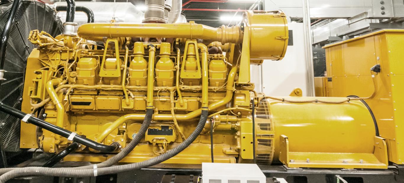
The Mechanism of Generating Electricity in Generators
An electrical machine is a device that can convert mechanical energy into electrical energy or vice versa, electrical energy into mechanical energy. An electric machine that produces electrical energy from mechanical energy is known as a generator. The process of generating electricity in a generator almost certainly utilizes a magnetic field. In other words, the magnetic field becomes a fundamental mechanism that plays an important role in the process of converting electrical energy.
The presence of a magnetic field in a place will affect the surrounding environment. One of the effects of the magnetic field which is used as the basic principle of generator work is: If there is a conductor material, for example: a wire, moving at a certain speed and passing through a magnetic field, an electric voltage is induced on the moving wire as a result of the magnetic field. the. This can be illustrated by the following formula:
eind = (v x B).L
eind = Voltage produced as a result of a magnetic field on a conductor moving past it
v = Relative velocity of the conductor
B = Magnetic flux
L = Length of conductor exposed to magnetic field
As seen in the formula above, the induced voltage is influenced by three parameters, namely the speed of movement of the conductor, the magnetic field and the length of the conductor. This formula also describes the change in energy form from mechanical energy in the form of kinetic energy (represented by velocity, v) to electrical energy (represented by voltage, eind).
The formula above is the parent of the more complex derivative formulas that are applied to the working mechanism of the generator. Keep in mind that the velocity referred to in the above formula is the relative velocity between the conductor and the magnetic field. This is, the formula above still applies if the conductor is at rest but the magnetic field is moving, which is certain as long as there is relative motion between the two, then the voltage will be induced on the conductor.
The two main components of a generator are the rotating component known as the rotor and the stationary component known as the stator. The rotor is designed to have a magnetic field by implanting magnets in the rotor or by providing DC current to the rotor. Either by using permanent magnets or providing DC currents, both of which produce a magnetic field in the rotor which will affect the surrounding environment.
The main part of the stator is a set of three coils of conducting material which is usually made of iron or aluminium. The three coils are each separated by a 120o angle as shown in Figure 1. The first coil is a'-a, the second is b'-b and the third is c'-c. The purpose of the three coils with a relative angle of 120o is to produce three-phase electricity. When the rotor rotates, the magnetic field in the rotor also rotates. With the relative motion between the magnetic field and the coils on the stator, the voltage on each coil will be induced with the same magnitude but with a different phase of 120o. If a load is connected to the stator, which now has an electric voltage, the current will flow to the load.
Figure 1. The Stator in an Electric Generator
An integrated system mechanism is required to produce a rotating rotor. The working principle of the mechanism is to combine the rotor/ stator with a continuous rotation generating system. In other words, the rotating rotor is an extension of the rotating shaft of the continuous rotation system mechanism as shown in the figure below.
Figure 2. Rotation transmission in turbines and generators
Author


 53350
53350


 15 Mar 2022
 7347 kali


