
02 July 2019
 12254
12254
12254


Marine
1. Transducer
2. Transponder
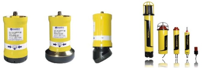
3. Beacon
Beacon is a transmitter that send specific signal from the bottom of the sea. This equipment send out the signal continuously. In addition, beacon usually also called by pinger [2][3].
4. Hydrophone
Hydrophone function is only for receive the reply signal that send out from transponder or beacon [2][3].
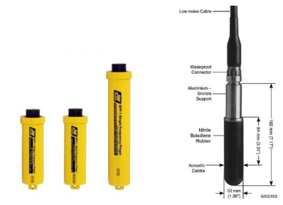
Figure 2 Left Picture is Beacon/Pinger and Right
Picture is Hydrophone [6[7]
1. UK H. Surface Positioning System. Presentation presented at; 2015; Hydrofest.
Acoustic Positioning for Oil and Gas Industry
1.0 Introduction
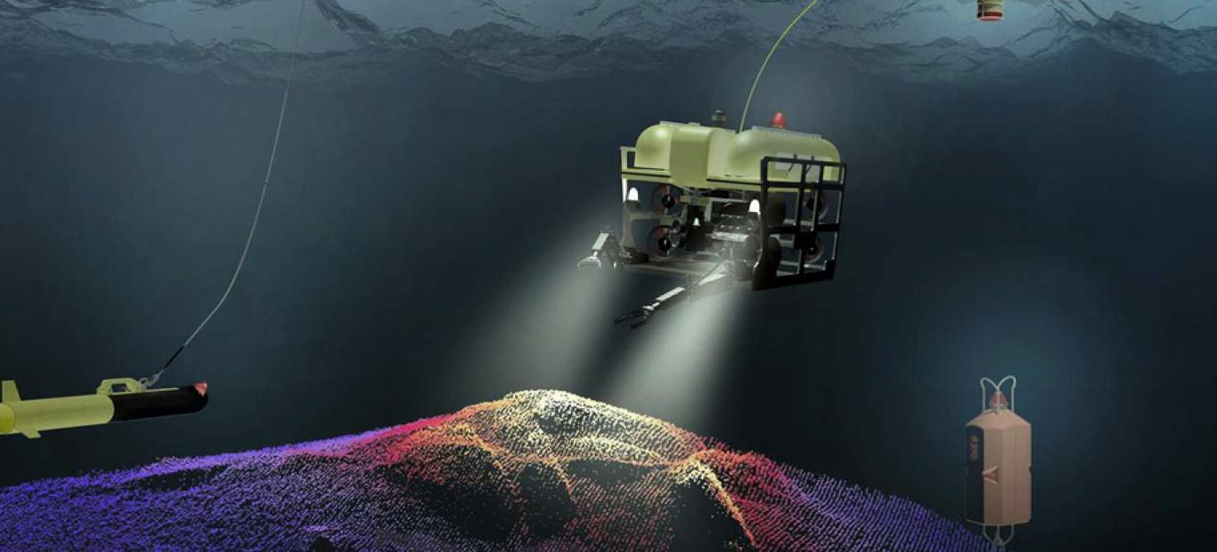
Acoustic positioning has a very high impact to oil and gas industry. From its terminology, acoustic positioning is a method to determine position with utilizing acoustic wave that propagate through seawater. In general, this kind of positioning use five type of instrument, there are:
1. Transducer
Transducer is an equipment that not only can send initial command, but also receive the reply signal. In other words, transducer has two role, first as transmitter and second as receiver [2][3]. This two role happened respectively by begin with transmission process. Transducer convert electrical energy into sound energy which will become the initial signal [4]. The characteristic of the signal that being send is different with signal that being received. It means that the signal has different frequency.
2. Transponder
The function of transponder is similar with transducer. The only difference between these instruments is the sequence [4]. Transponder receive the signal first, and then transmit the reply signal with different frequency from received signal. In addition, this equipment work corresponded with transducer [2][3].
Figure 1 Left Picture is Transducer and Left Picture is Transponder [3][5]
3. Beacon
Beacon is a transmitter that send specific signal from the bottom of the sea. This equipment send out the signal continuously. In addition, beacon usually also called by pinger [2][3].
4. Hydrophone
Hydrophone function is only for receive the reply signal that send out from transponder or beacon [2][3].
Figure 2 Left Picture is Beacon/Pinger and Right
Picture is Hydrophone [6[7]
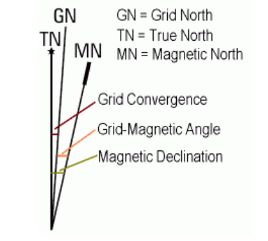
There is other equipment that not categorized as underwater acoustic positioning, called gyro. The function of gyro is to measure heading relative to true north. This measurement need to consider the grid north and true north direction. The angle between those two lines called the grid convergence [grid convergence]. The function of these grid is to change an azimuth to a bearing. That is to say, to get the value of bearing, needed to consider the grid convergence and azimuth value. In addition, there also other term that express the north direction in earth. It called Magnetic North. In this starling spool metrology, we do not use this magnetic north.
Figure 3 Grid North, True North, and Magnetic North[8]
2.0 Acoustic Positioning Type
Based on the length of their baseline, there are three classification of acoustic positioning system [9]:
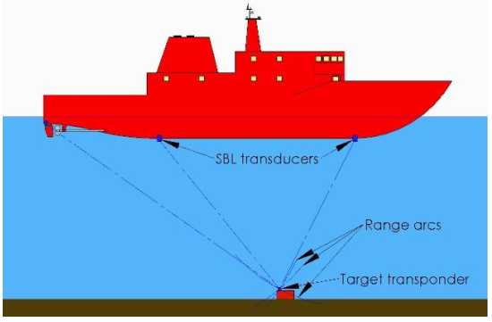
1. Short Baseline (SBL)
Short Base Line (SBL) acoustic positioning use hydrophone or transducer that attach to the surface vessel and also use underwater transponder. Usually, the amount of transducer on vessel is three. It is called Short Baseline if the distance between each transponder is from 5m until 20m [3].
Figure 4 SBL Configuration [11]
Simply, in SBL system, the position of transponder is determine by calculating the intersection point of three line from transducer on the vessel [2]. This calculation really depend on surface vessel, particularly on baseline distance between transducer [10]. If the gap is shorter, the accuracy will reduce because it is too narrow and the intersection tend to become a larger point, even become a line.
UBSEA CONSTRUCTION, INSPECTION, AND MAINTENANCE
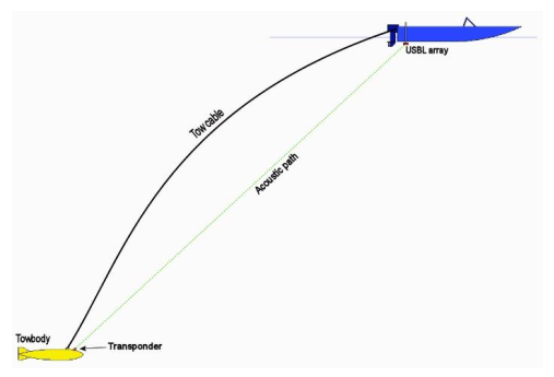
2. Ultra-short Baseline (USBL)
2. Ultra-short Baseline (USBL)
Basically, USBL and SBL is same. The process is send the signal from transducer on the surface vessel to transponder on the seabed. The difference between those two systems are the amount of transducer. In USBL system, there are only one transducer that attach on surface vessel and its size is very small, the diameter only 230mm. It can be happened because of new innovation of microprocessor [2].
Figure 5 Principle and sequence of USBL[11]
Generally, the sequence process of USBL are
a. USBL transducer on the surface vessel send acoustic signal to transponder
b. The transponder receives the signal and send reply signal to transducer
c. The sound speed is used to calculate the distance
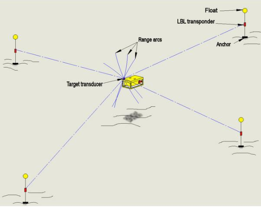
2. Long Baseline (LBL)
Long Baseline (LBL) system is an acoustic positioning method use very long baseline distance between transponder and consequently, the coverage area is quite wide. The value of the baseline distance is vary, depend on several things such as water depth, sound frequency, and seabed surface characteristics.
Figure 6 Principle and sequence of LBL[11],
Basic principal of the LBL process is the mobile transceiver send signal to transponder and will reply with different signal frequency. Then with the sound velocity and the time to spend one signal until reach the receiver, distance can be calculated. The advantages of this method is the redundancy of measuring the distance [10]. The redundancy is help to increase the measurement accuracy. However, LBL also have several disadvantages such as need expert for performing the method and costly.
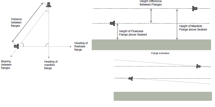
3.0 Spool Piece Metrology
Spool Piece Metrology is a measurement position and location of spool. There are several purpose why should perform spool piece metrology, there are:
a. Measure the distance between flanges
b. Measure flanges direction
c. Calculate height difference between flanges
d. Relative depth along spool to flanges
Figure 7 items to calculate in spool piece metrology [3}
To perform spool metrology, there are several method that common in subsea industry. There are [12]:
a. LBL Acoustic Metrology
Basically this method apply the LBL that already explain before. This measurement method really depend on speed of sound under the water. In addition, this method is used widely because the result can be obtained in a short time.
b. Diver Taut Wire Metrology
This method is connect one hub to other hub with tape. Surprisingly, this was the first method of subsea metrology did by divers.
c. Digital Taut Wire Metrology
This is an improvement from diver taut wire metrology. This method is primarily use ROV as the ‘tape’ installer. However, diver still can use this method
d. Photogrammetry
Basically, this method utilize triangulation to create 3D model. The triangulation itself come from the imaginary line that created by two or more locations. This line will have intersection to produce the coordinate.
4.0 Summary
Positioning is consider as one of the most important aspect in oil and gas industry. This terms is dividedinto two categories, surface and underwater. On the surface positioning, people tend to use GlobalNavigation Satellite System (GNSS) as method to determine location of vessel, equipment, etc. One ofthe most common type of GNSS is GPS (Global Positioning System) [1]. Along with the developmentof oil and gas industry, the exploration of hydrocarbon move from onshore to offshore, then reach deepwater. This phenomena push expertise to use underwater positioning to measure location of equipmentand instrument below the water surface.
References
1. UK H. Surface Positioning System. Presentation presented at; 2015; Hydrofest.
2. Milne P. Underwater engineering surveys. Houston: Gulf Pub. Co., Book Pub. Division;1980.
3. Winning S. Subsea Survey, Positioning, and Metrology. Presentation presented at; 2015; University of Aberdeen.
4. Engineering E. What is the difference between Trancducer and transponder? [Internet]. Physics Forums - The Fusion of Science and Community. 2015 [cited 1 March 2015]. Available from: https://www.physicsforums.com/threads/what-is-the-differencebetween-trancducer-and-transponder.574053/
5. Staff S. Subsea World News | The industry's subsea news provider [Internet]. Subseaworldnews.com. 2015 [cited 1 March 2015]. Available from: http://subseaworldnews.com
6. Kjaer B. [Internet]. Bksv.com. 2015 [cited 1 March 2015]. Available from:http://www.bksv.com/~/media/New_Products/transducers/hydrophones/drawing208106.ashx?mh=600&mw=600&bc=white
7. Cdn-media.metaldetector.com. [Internet]. 2015 [cited 1 March 2015]. Available from:http://cdnmedia.metaldetector.com/media/catalog/product/cache/1/image/400x400/9df78eab33525d08d6e5fb8d27136e95/p/r/productpingershr_5.jpg
8. Physicalgeography.net. Geography : Physical Geography [Internet]. 2015 [cited 2 March 2015]. Available from: http://www.physicalgeography.net
9. Geyer R. Handbook of geophysical exploration at sea. Boca Raton, Floride: CRC Press;1983.
10. Bai Y, Bai Q. Subsea engineering handbook. Burlington, MA: Gulf Professional Pub.;2010. 11. http://www.amloceanographic.com/ [Internet]2015[cited 1 March 2015]. Available from: http://www.amloceanographic.com/Technical-Demo/USBL-SBL-LBL_2
12. Guidance of Subsea mEtrology. 1st ed. 2012.
Penulis

Yanuardy Rahmat M., ST., M.Sc.
Email: yanuardy@indonesiare.co.id
Artikel
- Pipe In Pipe System In Oil and Gas Industry (Part I)
 06 Aug 2021
 10981 kali
 - Part I: Automatic Termination/ Pembatalan Polis Otomatis pada Asuransi Rangka Kapal (Marine Hull)30 Jul 20217758 kali
- Part 2 - Proteksi kepada Perusahaan Pelayaran dari Dampak COVID-1921 Apr 202010012 kali
- Part I - Proteksi kepada Perusahaan Pelayaran dari Dampak COVID-1913 Apr 20208505 kali
- Pipe-laying Method in Offshore / Subsea Construction23 Mar 202025885 kali
- Application of Fibre Optic Cables in Offshore and Subsea Environment18 Feb 201915252 kali
- Agile Organization : The Answer of Current Business Environment29 Jan 201910845 kali
Follow Us


